1 Verify the O2 sensor Heater 1/Heater 2 is on. Tuning Link automatically enables required sensor heaters (if any) in all modes except Break-In/Warmup. To disable the sensor heaters, switch to Break-In/Warmup and toggle the heater button off. Switching to any other mode will automatically re-enable the sensor heaters.
2 Using the drop-down menu, select a tuning mode.
Steady State Mapping—Click a cell in the column you want to tune. The software will automatically move to the next RPM cell once it is within the set error threshold. Use steady state mapping for fine tuning cells in a particular column. Also good for low throttle positions.
Roll-on Mapping—Click a cell in the column you want to tune. Once this target is reached, the dyno will allow the bike to roll through the RPM range. It will slow the drum down to the starting cell automatically. Use roll on mapping as a quick way to tune the cells in all the columns.
Live Tune Mode—The software will achieve your target AFR no matter where you are in the table. This is good to use when mapping a vehicle with electronic throttle. Live Tune Mode takes more time.
3 If you are using Cell Trace, verify Cell Trace is on. From the View ribbon, click the Cell Trace button.
Cell Trace shows your location in the table in real time. Cell Trace uses significant processing power and is optional, although it is recommended.
4 Choose which table you wish to view during tuning. In the example below, the Fuel Adjust Table is used.
Percent Error Tables—the values in this table represent the percent difference between the target air fuel and the actual air fuel.
5 Click on a cell to begin tuning.
In the example below, we have chosen the cell at 25% throttle and 4500 RPM. The cell you have chosen will have a black circle until the cell tracer nears the chosen cell.
6 With the vehicle in gear, increase the throttle until the cell trace is in the starting cell (the blue plus sign).
When you are close to the starting cell, the circle turns yellow. When the circle turns green, tuning will begin and the dyno will allow the vehicle to accelerate.
7 Maintain the same throttle position until maximum RPM is reached then close the throttle.
The dyno will allow the vehicle to decelerate back to the starting point and the percent error values will update.
To further tune that column increase the throttle until the cell trace is back at the starting point or choose a new starting point.
If you are viewing the percent error table, cell colors represent how close each cell is to the target value.
White Cell—cell not read.
Green Cell—cell is tuned and is within your set error percent.
Red Cell—cell is tuned, but the target has not been reached. You may want to tune that cell/column again.
8 Continue the tuning process until your whole map is filled in.
Note: It may not be possible to fill every cell. For the lower position columns it may be more efficient to use steady state mapping.
9 Click the Save button to save your map to your computer for future use.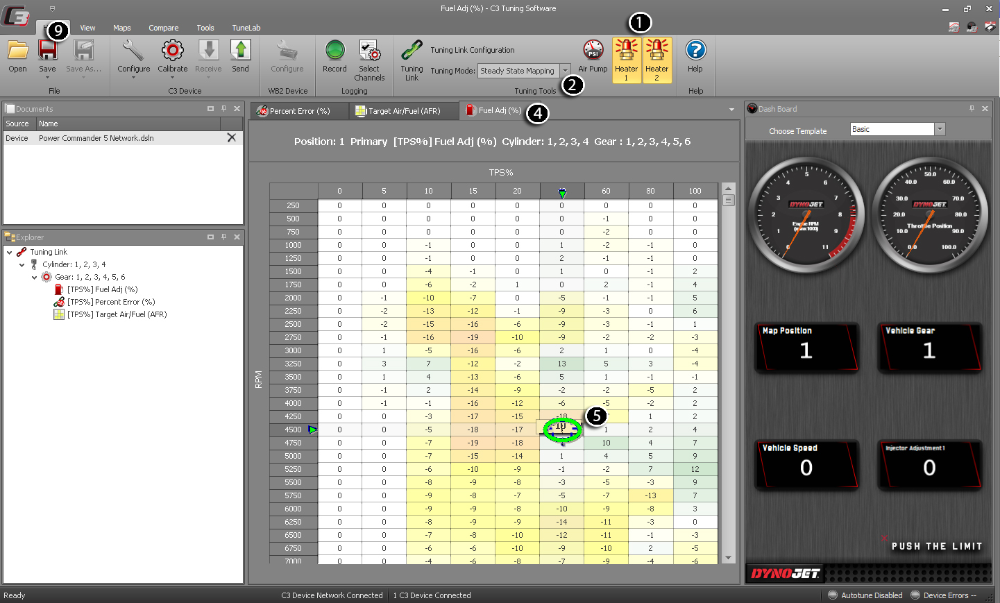
Related Topics